|
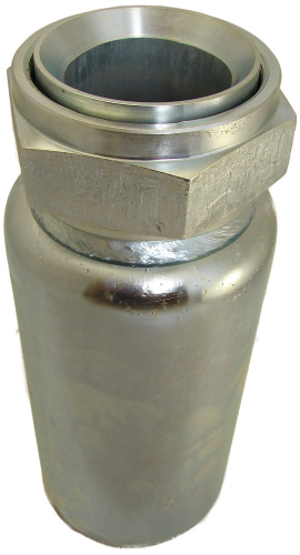
End Styles:
SAE Code 61 and Code 62, Split Flanges,
Code 61 Block, O-Ring and Flat Face and Male NPT. Other materials are
available such as stainless steel 316.
Hose Applications: High
Pressure Wire Braided Hydraulic Hose.
|
SIZE |
|
WORKING |
|
TYPE |
|
STEM |
|
|
|
ASSY. |
|
HOSE O.D.
SIZE RANGE |
PRESS./ PSI |
PART
NUMBER |
STEM
I.D. |
MEAN O.D. |
FERRULE
O.D. X I.D. |
OVERALL LENGTH |
HOSE
C.O.F.* |
WT. LBS. |
|
2 1/2" |
3 3/16 - 3 3/8 |
1,600 |
940HX+640 |
SAE 37" Swivel (JIC) |
2 1/8 |
2 15/32 |
4 X 3 5/8 |
11 1/4 |
3 1/4 |
10.0 |
|
3 3/16 - 3 3/8 |
1,600 |
940HX+740A |
Code 61 Fig Straight |
2 3/32 |
2 1/2 |
4 X 3 9/16 |
11 3/8 |
5 1/4 |
12.0 |
|
3 3/8 - 3 5/8 |
1,600 |
940HX+740B |
Code 61 Fig Straight |
2 3/32 |
2 1/2 |
4 1/4 X 3 3/4 |
11 3/8 |
5 1/4 |
12.0 |
|
3 3/16 - 3 3/8 |
1,600 |
940HX+740A-45 |
Code 61 Fig 45° |
2 3/32 |
2 1/2 |
4 X 3 9/16 |
13 15/16 |
7 3/4 |
15.3 |
|
3 3/8 - 3 5/8 |
1,600 |
940HX+740B-45 |
Code 61 Fig 45° |
2 3/32 |
2 1/2 |
4 1/4 X 3 3/4 |
13 15/16 |
7 3/4 |
15.3 |
|
3 3/16 - 3 3/8 |
1,600 |
940HX+740A-90 |
Code 61 Fig 90° |
2 3/32 |
2 1/2 |
4 X 3 9/16 |
12 1/8 |
5 7/8 |
16.0 |
|
3 3/8 - 3 5/8 |
1,600 |
940HX+740B-90 |
Code 61 Fig 90° |
2 3/32 |
2 1/2 |
4 1/4 X 3 3/4 |
12 1/8 |
5 7/8 |
16.0 |
|
3" |
311/16 - 3 7/8 |
1,200 |
948HX+748A |
Code 61 Fig Straight |
2 7/16 |
3 |
4 1/2 X 4 |
13 3/8 |
5 |
18.0 |
|
3 7/8 - 4 3/8 |
1,200 |
948HX+748B |
Code 61 Fig Straight |
2 7/16 |
3 |
5 x 4 1/2 |
13 3/8 |
5 |
18.7 |
|
3 11/16 - 3 7/8 |
1,200 |
948HX+748A-45 |
Code 61 Fig 45° |
2 7/16 |
3 |
4 1/2 X 4 |
16 3/8 |
8 3/4 |
21.5 |
|
3 7/8 - 4 3/8 |
1,200 |
948HX+748B-45 |
Code 61 Fig 45° |
2 7/16 |
3 |
5 x 4 1/2 |
16 3/8 |
8 3/4 |
22.2 |
|
3 11/16 - 3 7/8 |
1,200 |
948HX+748A-90 |
Code 61 Fig 90° |
2 7/16 |
3 |
4 1/2 X 4 |
14 5/8 |
6 1/4 |
22.5 |
|
3 7/8 - 4 3/8 |
1,200 |
948HX+748B-90 |
Code 61 Fig 90° |
2 7/16 |
3 |
5 x 4 1/2 |
14 5/8 |
6 1/4 |
23.2 |
|
|
|
|
|
|
|
|
|
|
|
|